Every deck deserves a special signature. The Trex Signature® X-Series™ Cable Rail offers a modern look, unobstructed views and more design flexibility. The versatile X-Series anchor post can be configured for use as an end, line and corner post. Additionally, novel spring-loaded cables offer improved tension management so that cables are less prone to sag over time, while push-to-connect fittings eliminate swaging or crimping.
Please check with the local municipality for code requirements.
Step 1: Installing X-Series Posts on Pressure-Treated Wood Framing
Installing Blocking at Corners: Install 2" x 8" cross bracing frame in between joists at 7-1/4". Attach using a total of (12) 3" pressure-treated compatible wood screws. Then, install (2) 2" x 8" boards as blocking under post location. Securely attach blocking using a total of (24) 3" pressure-treated compatible wood screws.
Installing Blocking on Straight Runs: Install (2) 2" x 8" cross bracing frames in between joists at 7-1/4". Attach using a total of (12) 3" pressure-treated compatible wood screws. Then, install (2) 2" x 8" boards as blocking under post location. Securely attach blocking using a total of (24) 3" pressure-treated compatible wood screws.
Step 2: Mounting X-Series Posts to Blocking
Determine edge of framing and measure in minimum 1" from this location. If measuring from corner, ensure 1" from each edge. Using post as template, mark location of holes for mounting bolts using 9/16" drill bit (long bit will be required). Set post aside and drill through decking and blocking using same 9/16" drill bit. Attach posts using (4) 1/2" x 6" hex bolts, washers, and tee nuts. Be sure to place washers in the correct location as shown.
IMPORTANT: Thread tee nut onto bolt until flush with end of bolt. Hammer tee nut into blocking until teeth fully engage with blocking. Be sure to hammer the tee nut and not the bolt itself. Using an impact driver with 3/4" socket, fully tighten bolts until post is secure. Do not push down on bolt while tightening. Use a level on sides of post to ensure post is plumb.
Tip: Slide corner covers up for easier access when installing bolts.
Step 3: Installing Pass-Through Posts
X-Series Horizontal Cable Rail is designed to be installed at a maximum clear span of 6', 12', or 18' between X-Series Anchor Posts. If not installing standard clear spans as listed above, you must first calculate the clear span between X-Series Anchor Posts, then divide accordingly, depending on total overall span. Any span over 6’ will require the use of one Pass-Through Post. Any span over 12’ will require the use of two Pass-Through Posts.
Install Pass-Through Posts using mounting hardware provided. When mounting Pass-Through Posts to pressure-treated wood framing, follow the same installation method and blocking details outlined in the Trex Signature X-Series Post installation instructions. Ensure Pass-Through Posts are plumb.
18' Post Placement - 6' (183 cm) Inside to Center, 6' (183 cm) Center to Center, 6' (183 cm) Center to Inside.
12' Post Placement - 6' (183 cm) Inside to Center and 6' (183 cm) Center to Inside.
6' Post Placement - 6' (183 cm) Inside to Center.
Step 4: Measuring and Cutting Top Rails (When Required)
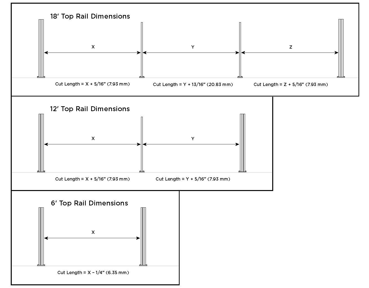
Measure each span separately. Do not assume all top rails will be identical in length.
18' Top Rail Dimensions - Cut Length = X + 5/16" (7.93 mm), Cut Length = Y + 13/16" (20.83 mm), Cut Length = Z + 5/16" (7.93 mm)
12' Top Rail Dimensions - Cut Length = X + 5/16" (7.93 mm) and Cut Length = Y + 5/16" (7.93 mm)
6' Top Rail Dimensions - Cut Length = X – 1/4" (6.35 mm)
NOTE: IF INSTALLING HORIZONTAL RAILS AT AN ANGLE, USE COMPOUND SWIVEL BRACKETS AND REFER TO INSTRUCTIONS AT THE END.
Step 5: Inserting Cables into Cable Infill Adapters
Insert short cables into cable infill adapter as shown. Then, insert long cables into opposite cable infill adapter as shown. Slide cable infill adapters into X-Series Anchor Posts as shown.
IMPORTANT: Cable infill adapter should be inserted so that the hole closest to the end is at the bottom of the post. The bottom infill adapter should be approximately 2-1/2” from the bottom. The top infill adapter should be approximately 3-1/4” from the top.
Step 6: Threading Long Cables Through Cable Brace(s) and Pass-Through Post(s)
Remove cover on end of cable. Thread the top cable through the top hole in the cable brace. Continue to thread this same cable through the top hole in the Pass-Through Post (when required). If you have multiple spans, continue in this fashion. Next, thread the bottom cable in the same manner. After installing the top and bottom cables, slide the cable brace next to the Pass-Through Post. Tip: Tape cable brace to Pass-Through Post for easier installation of remaining cables. Remove remaining cable covers and thread remaining cables through cable brace(s) and Pass-Through Post(s).
Step 7: Inserting Brackets onto Top Rails
Insert all brackets, ensuring they are fully seated. Using a 9/64” drill bit, pre-drill at all bracket locations as shown.
Note: Only pre-drill through the first layer of the rail and bracket.
Step 8: Installing Top Rails and Brackets onto Posts
For 18' spans (or spans that have 3 top rails), install center rail onto Pass-Through Posts first, then install outer rails on each side.
For 12' spans (or spans that have 2 top rails), install first rail onto X-Series Anchor Post and Pass-Through Post, then install remaining rail.
For 6' spans (or spans that have 1 top rail), install rail onto both X-Series Anchor Posts.
Step 9: Installing Top Rail Straight Brackets in X-Series Anchor Posts
Position the top rail straight bracket PARTIALLY into the X-Series Anchor Post as shown. Slide the top rail locking assembly onto the dovetail on the top of the bracket. Slide the bracket down until it sits on the cable infill adapter. Note that the screw in the locking assembly may need to be loosened to allow the locking assembly to fit properly in the X-Series Anchor Post. Tighten screw in locking assembly using a 5/32" Allen wrench.
Step 10: Fastening Pass-Through Post Bracket to Pass-Through Post (When Required)
Install two barrel bolts through Pass-Through Post as shown. Insert screw on opposite side and tighten using a 1/8” Allen wrench.
Step 11: Threading Push-to-Connect Fittings into Turnbuckles
Thread each push-to-connect (PTC) fitting into the turnbuckle on each short cable until the threads just disappear in the turnbuckle. Ensure threads are flush with the end of the turnbuckle.
Step 12: Cutting Long Cables (Safety Note: Wear safety glasses when cutting cables.)
Pull each long cable taut and straight by hand and mark cable at cut line on PTC fitting as shown. Cut each long cable on mark using cable cutters.
Step 13: Installing Long Cables into Push-to-Connect Fittings and Tensioning Cables
NOTE: If installing X-Series Cable Rail near saltwater environments, spray a small amount of WD-40 Specialist® Corrosion Inhibitor in the open end of the PTC fitting before inserting the cable. Do this IMMEDIATELY before inserting the cable to prevent dirt and dust from collecting inside the fitting. Use caution not to get this on the decking surface! Protect decking from drips and runs.
Push the end of each long cable into opposite PTC fitting, slightly rotating the PTC fitting counterclockwise and cable clockwise (approximately 1/4 turn) until cable is fully seated. Hand-tighten all cables by holding the PTC fitting fixed and rotating the turnbuckle. Do NOT rotate PTC fitting when tightening cables. Using the turnbuckle wrench(es) provided (one per kit), place one wrench on the flat sides of the PTC fitting. Place a second wrench on the turnbuckle as shown so that it locks in place with the cutouts on the end of the turnbuckle. Tension each cable to 100 lbs. by rotating the turnbuckle-side wrench. Do NOT rotate PTC fitting when tensioning cables. Tension cables from the center outward, following the sequence shown. Repeat sequence as necessary until all cables are fully tensioned.
Step 14: Centering Cable Brace(s)
Locate the center of each span and slide all cable braces to their center positions. Ensure that cable braces are straight/vertical, and then tighten both top and bottom set screws using a 3/32" Allen wrench.
Step 15: Fastening Top Rails to Brackets
Install #8 x 1/2" screws into pre-drilled holes in top rails to fasten top rails to brackets at each Pass-Through Post and X-Series Anchor Post.
Step 16: Final Installation Steps
Install top inserts into the open channel above each bracket in all X-Series Anchor Posts. Install post caps and bolt caps to complete installation. For bolt caps, align hex shadow line on inner cap with bolt head and snap into place; then push outer cap onto inner cap.
Installing Horizonal Cable Rail at an Angle
Follow all instructions as previously stated for standard horizontal installation EXCEPT for where noted below. Temporarily slide compound swivel bracket(s) into X-Series Anchor Posts. Adjust each compound swivel bracket to align with direction of top rail and hand-tighten screws using a 5/32" Allen wrench to temporarily stabilize the swivel bracket. Measure between brackets at location shown, add 5/8" (15.8 mm) and cut top rail to this length. Complete the remainder of the installation following the steps previously outlined. After installation is complete, tighten all screws in each compound swivel bracket using a 5/32" Allen wrench.


