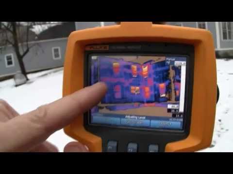
Water and air leaks in a building shell are difficult enough to detail on simple buildings. Complex structures can cause migraines for builders, remodelers, and architects who don't pick up their pens and trace at the design stage. Photo: courtesy of EPA
Developed as a fun way to shame young architects at Building Science Corporation HQ, The Pen Test is a fast and insightful way to discover how two-dimensional your three-dimensional thinking is.
The pen is mightier than the saw
On the building physics red carpet, liquid water gets the most attention and is the darling of the media. Insulation gets some airplay, but invisible to most pundits is air, whose ability to carry moisture can be devastatingly deceptive.
Building durability and efficiency depend on controlling water, heat, and air flow. This article is about doing that with a pen and a piece of tracing paper.
Liquid is the most obvious damage function
Liquid water damage can come in the form of wind-driven rain, flashing failures, roof leaks, or plumbing leaks. We're not going to talk about plumbing leaks here, but that doesn't mean they should be ignored. We'll talk about plumbing leaks later.
Liquid water that comes from the sky is controlled with a (wait for it ...) liquid control layer.
(Worth the wait?)
It is composed of flashings, drainage planes, and capillary breaks all working together as a team.
Vapor drive changes with the seasons
Moisture in the form of vapor usually leaks into assemblies on air currents, which can come from the inside or outside, depending on the season.
An air-conditioned house during a hot, humid summer tends to suck vapor into the walls from the outside. In winter, the reverse happens: Humid air from inside the house is driven into the walls through holes like electrical outlets, can lights, and unsealed interior soffits.
This is called vapor drive: movement of moisture in response to concentration differentials. Moisture moves from wet to dry, and from warm to cool.
As soon as warm moist air hits a cool surface (the plywood wall sheathing or the drywall, depending on the direction of drive), the vapor condenses into liquid and puddles in the cavity, out of sight from homeowners (and remodelers).
Heat flow can be predicted, too
Physics has been smugly pointing out for years that heat moves from more to less, just like water.
You can feel it moving out of you when you stand next to a single-pane window on a cold day, and you can feel it bombard you next to that same window on a sunny one.
(If physics weren't so smug, maybe more people would like physics. Just sayin'.)
If you can't draw it, they can't build it
The Pen Test is widely talked about in building science circles, but it is not widely talked about in day-to-day home building and remodeling. The idea is that if you can draw a line on the building section showing where the air barrier, the drainage plane, and the thermal barrier are located—and that line is continuous—then the assembly can be built to work. But if you can't draw it, it isn't there.
Many building scientists joke that they break in new architects and engineers by putting them through The Pen Test on various blue prints.
The EPA has an illustrated explanation of The Pen Test in their Moisture Control Guidance for Building, Design, Construction, and Maintenance.
" ... it's like a parachute: There's no law requiring you to use one, but it's a good idea."
—Lew Harriman, one of the principal contributors on using the guide.
Appendix A of that guide is reprinted with permission here
The images are typical of commercial construction and many urban residential buildings: brick cladding, parapet roof, gypsum sheathing, but don't let that scare you off.
Regardless of whether you're working on a Cape Cod in New England, a row house in San Francisco, an ultramodern dwelling in Seattle, or a farmhouse in Iowa, the principle holds: If you can't draw the water control layer, the heat control layer, and the air control layer, then they won't get built.
—The moisture control guide was written by Terry Brennan, Michael Clarkin, and Lew Harriman.
We would like to thank them for doing this work because it is important stuff and a lot of folks don't know the details.
<!------Begin EPA Doc------>
PURPOSE
By tracing the continuity of all the materials for each control function, the “pen test” checks the completeness of:
- Rainwater protection
- The insulation layer
- The air barrier
To verify continuity, create sections in which each of these moisture-control elements is traced in a different color to show that the design specifically accounts for them. Contractors can then easily check the sections against their experience with materials, trades, and sequencing. The sections will also provide maintenance workers in buildings and grounds with information useful in ordinary maintenance work or in the event of a problem during building use.
PROCESS
Rainwater Layer Continuity
To demonstrate complete rainwater protection using the section drawing, place a pen on a material that forms a capillary break between the rain-control materials that get wet and the inner portion of the enclosure that must stay dry. Without lifting the pen off the paper, trace from the center of the roof around the walls, windows, and doors and along the foundation to the center of the foundation floor.
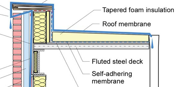
Figure A-1 serves as documentation of rainwater protection continuity. The following describes the traceable capillary break in a sample section. Starting at the center of the roof:
- The roofing membrane is the first line of defense, protecting the water-sensitive inner materials from rain and snowmelt.
- Tracing the roofing membrane from the center of the roof to the edge of the roof, the roofing membrane rises up the parapet wall where it flashes beneath a metal coping, which also forms a metal fascia.
- The fascia forms a drip edge, channeling water away from the cladding.
- An air gap between the drip edge and the brick veneer forms a capillary break, protecting the materials beneath the coping from rainwater.
- Behind the brick veneer, air gap, and foam board, a self-adhering water resistant barrier (WRB) applied to the gypsum sheathing forms a capillary break between the damp brick and the inner wall assembly.
- The WRB laps over the vertical leg of a head flashing, protecting the window from rainwater with a drip edge and an air gap. Weep holes allow water to drain from behind the brick cladding.
- The window frame, sash, and glazing form a capillary break system that sits in a pan sill flashing at the bottom of the window.
- The pan sill flashing forms a capillary break protecting the wall beneath from seepage through the window system.
- The pan sill flashing shingles over the WRB in the wall beneath, which shingles over a flashing that protects the bottom of the wall system.
- The water-resistant barrier shingles over a flashing that protects the bottom of the wall system, where the foam sill seal makes a capillary break between the foundation and the bottom of the framed wall, connecting with:
- One inch of extruded styrene foam insulation making a capillary break between the top of the foundation wall and the edge of the floor slab.
- Polyethylene film immediately beneath the slab forms a capillary break between the bottom of the slab and the fill below. NOTE: If the bed of fill beneath the slab consists of pebbles greater than ¼ inch in diameter and contains no fines, then it forms a capillary break between the soil and the slab. Apply the same procedure to the insulation layer and the air barrier.
Insulation Layer Continuity
To demonstrate a continuous layer of insulating material around a section, place the pen tip on the insulating layer in the center of the roof and trace from one insulating material to the next around to either the bottom of the foundation wall or the center of the foundation floor.
Figure A-2 shows the continuity of thermal insulation in a sample section.
- Beginning at the center of the roof, trace through foam insulation to the edge of the roof.
- Up a layer of foam board insulation to the wooden blocking at the top of the parapet wall.
- The wooden blocking connects to the top of the exterior foam insulation board insulation and the top channel of the light gauge wall framing.
- The steel wall framing is filled with cavity insulation, and the thermal bridge through the steel is insulated by the exterior foam insulation.
- At the window head, the steel lintel is a thermal bridge through the insulation system, the rough opening around the window is sealed using backer rod and sealant.
- The window jamb, sash and glazing system provide insulation continuity to the pan sill flashing at the bottom of the window.
- The exterior insulating foam sheathing and cavity insulation carry the insulation layer to the foundation.
- Foam sill seal provides thermal insulation between the bottom of the wall and the concrete foundation, which carries thermal protection below grade to the bottom of the foundation wall.
- Vertical foam insulation applied to the interior of the foundation wall completes the insulation layer.
Air Barrier Continuity
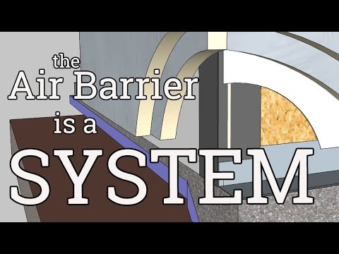
Continuity of the air barrier is demonstrated using the same method used for rainwater control and the insulation layer. For this example air barrier materials and the sealants used to connect them are identified from the center of the roof to the center of the foundation floor. Self-adhering membranes are used as examples in this section, but note that wall air barriers may be formed using alternate air barrier materials (e.g., fluid applied membranes, flexible sheets, rigid foam board insulation, and spray polyurethane foam).
- From the center of the roof trace the air along the self-adhering membrane on the gypsum roof sheathing to the edge of the roof.
- The self-adhering membrane continues up the gypsum board sheathing on the parapet wall where it connects to a transition membrane that spans the top of the parapet wall.
- From the transition membrane trace down the self-adhering membrane on the wall sheathing to an intersection with the window head flashing at the steel lintel.
- A transition membrane wraps from the bottom of the steel lintel into the rough opening where it connects to the window by sealant and backer rod.
- The window system forms the air barrier to the pan sill flashing where sealant makes the connection.
- The pan sill flashing carries the air barrier to the self-adhering membrane on the lower wall.
- A transition membrane connects to the concrete foundation.
- Polyethylene film or the concrete slab itself extend the air barrier to the center of the floor.
<!-------end EPA document------>
Go to the Source:
Moisture Control Guide from EPA.gov/iaq/moisture
