It is not difficult to build a home that produces more energy than it consumes. The science has been settled for years, and the systems are available.
In this episode of "Cup of Joe," host Joseph Lstiburek, Ph.D., P.Eng., ASHRAE Fellow, invites Betsy Pettit, FAIA, managing partner of Building Science Corporation, to explain the design and systems behind a Net positive test house BSC worked on with the National Institutes of Standards and Technology (NIST) back in 2014. Building Science Corporation did the design work as part of the Department of Energy's Building America program.
This house was "lived in" by robots who simulated the actions of people taking showers, cooking meals opening and closing doors, etc. Over time, the house was shown to be a net positive energy producer.
In general, solar panels are still "the badge of honor you get to install on an energy-efficient house" (Marc Rosenbaum quote) because using less energy is always the cheapest route to net zero. Here's how that breaks down.
1/ A solid set of plans
Set of drawings that declare the importance of air and water management through detailing and specificity. If you don't draw it, they won't build it. Because the assemblies are not "the same old way" of doing things, it is critical for the plans to specify the sequencing and detailing of assembly connections.
The BSC plan set included an axonometric drawing showing the installation sequence of the basement water barrier among its detail set.
2/ A simple shape
Above grade, they built boxes with no overhangs. The walls were framed with wood studs at 24-inches on-center, sheathed with plywood, and covered with a fully-adhered (peel and stick, paint-on, etc.) membrane for the WRB.
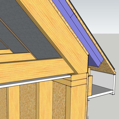
No overhangs were built into the box; instead, they were built ONTO it after the box was water- and air-tight. The final shape of the box is that of a cube with a pitched roof.
This approach yields ultra-low air leakage: .5 ACH50 on the initial test before holes for windows were cut and windows were installed.
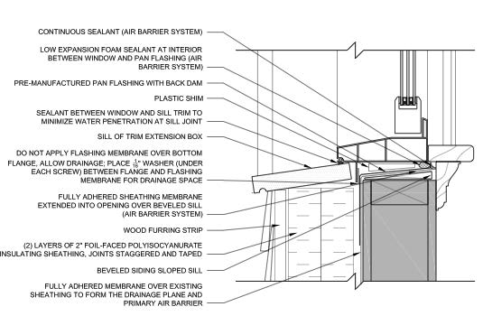
The window installation is where your airsealing and water management can go for naught, so it is a good place to pay attention. The windows in the test house were outies—in the plane of the outside wall surface. When building a thick-walled house, you can install windows to be innies, outies, or in-betweenies; it is a design choice.
3/ Continuous exterior insulation
Insulation fills the stud cavities as usual, and it is also wrapped around "the box" outside the self-adhered WRB.
Pettit used blown cellulose in the wall cavities—it could have been fiberglass, it could have been rock wool, it could have been shredded Levis. They chose cellulose because they like cellulose.
Continuous rigid insulation on the outside—the design team chose foil-faced polyisocyanurate, but any kind of rigid insulation (fiberglass, expanded polystyrene, rock wool, expanded polystyrene) could also have been used. They chose foil-faced polyiso for its high R-value, low GHG impact, and impermeable surface.
The choice of insulation is up to the people making the choice. Some choices are better for GHGs, some are more locally available, and some are itchier—it depends on what you like.
4/ Get the layers in order
Whatever insulations you choose, design the layers to allow the wall to dry. In other words, design the wall not to trap water.
Outside the plywood, Betsy's team used an impermeable fully-adhered membrane for the water- and air-control layer, so the wall must be able to dry toward the outside from that membrane and also toward the inside from that line.
Betsy points out that there was no plastic vapor barrier inside the wall, usually placed right behind the drywall. There are very few places in North America where a plastic vapor barrier makes sense—the coldest climate zones of the continent, far north of Chicago or Boston. With no plastic vapor barrier, the wall can dry to the inside.
The foil-faced polyisocyanurate extends the impermeable layer out from the membrane to the outer face of the foam. With furring strips outside the foil-faced foam, the siding is back-ventilated and can dry.
5/ Balance the ventilation equipment to provide fresh makeup air
The biggest box in the ventilation system is the HRV, which provides makeup air to all major exhaust appliances, like the kitchen range hood and the clothes drier.
An intermittent interlocked fan pulls new air in whenever the range hood or clothes drier is turned on. This balanced airflow eliminates positive and negative pressures that can suck moisture into walls.
Aside from opening and closing the doors, the bathroom exhaust fans are the only unbalanced aspect of the ventilation system. The robots turned them on and off intermittently (at shower times), and the fans were not tied into the makeup air system.
6/ The last step is producing energy on the roof
There are two energy sources in this test house:
- A 10k photovoltaic array is installed on the roof over unconditioned space.
- A solar hot water system is installed over conditioned space because solar water heating systems must conserve heat energy.
The house is 2,700 square feet above grade, another 1,300 square feet below grade, for a total of about 4,000 square feet of conditioned space.
The house was kept at 70 degrees F during winter and 72F during summer and dehumidified when needed. It never needed humidification, and the robots' comfort levels were always within ASHRAE's comfort guidelines.
Building Science Corporation's thermal recommendations: 1, 5, 10, 20, 40, 60
A simple shorthand for Net Zero R-value targets is as follows:
1, 5, 10, 20, 40, 60
- 1: the ACH50 target. 1 ACH@50pa
- 5: R-5 for the windows
- 10: R-10 for the sub-slab insulation in the basement
- 20: R-20 for below-grade wall insulation
- 40: R-40 for the wall insulation
- 60: R-60 for the roof/ceiling insulation
1, 5, 10, 20, 40, and 60 are general numbers, but if combined with a balanced ventilation system and 10kw of PV, they can get any house to net zero in climate zones three through six, which is a giant swath of the United States.
